Where I work, we are starting to look into doing continuous integration. One thing that my manager wanted was a build traffic light, so I built one.It ended up being quite simple to build really. So here is how I built it.
Parts List
- IC Station Micro USB controlled 5v 4-Channel Relay Module
- 1 micro USB cable (to power and control the relay)
- 1 USB cable you are willing to cut the end off. This will supply power to the LED’s
- 1 Red LED
- 1 Amber led
- 1 green led
- Optionally, another colour LED as the relay module has 4 channels. For my implementation, I chose blue.
- Resistors. Check the specs of the LED’s but 100-150 ohm should do the trick. I used 150 Ohm.
- Wire – at least 2 different colours (red and black)
- Heat shrink
- A plastic case to house it in.
- A Windows PC. You could probably use Mac or Linux, but the software that comes wi the device is Windows only and it’s better to start with when playing around.
- Solder
- Electrical tape
- Multimeter
Tools required
- Soldering iron
- Needle nose pliers and a wire cutter if your pliers doesn’t have one.
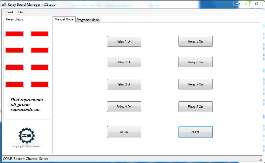
First things first, connect up the relay to a PC. Install the software and try to get the relay module to turn on and off. You will need to make sure that the relay module connects up to a com port lower than 5, if your port is recognized as higher, then try changing sub ports.
Also, you will need to install the driver. This should automatically install if your windows pic is connected to the Internet.
Using the software, you should be able to turn individual relays on and off.

Once you have the relay module working, the next step is to build the circuit.

The reason for the resistors is so that the full current does not short out the circuit and blow the power or the diodes.
A little bit of background. An LED will only light up when you when the current flows in a certain direction. So if you have the positive and negative e wrong way around, the LED will not light up.
Usually, the anode is the side where the wire is a little longer, but the best method is to hook up the led to a battery and see which direction causes the LED to light up.
Start off by soldering one of the resistors to the Anode of the LED. You may want to clip the anode wire a little so it doesn’t look too long.. Repeat this for all the remaining LEDs.
Next, solder the wires to the Resistors and the LED cathode. I prefer to use a different color wire for each anode. For example, to match the colours of the LED. For the cathode (negative) side I used the traditional black.
Put heat shrink around each join
Each switch is one of the relay switches.
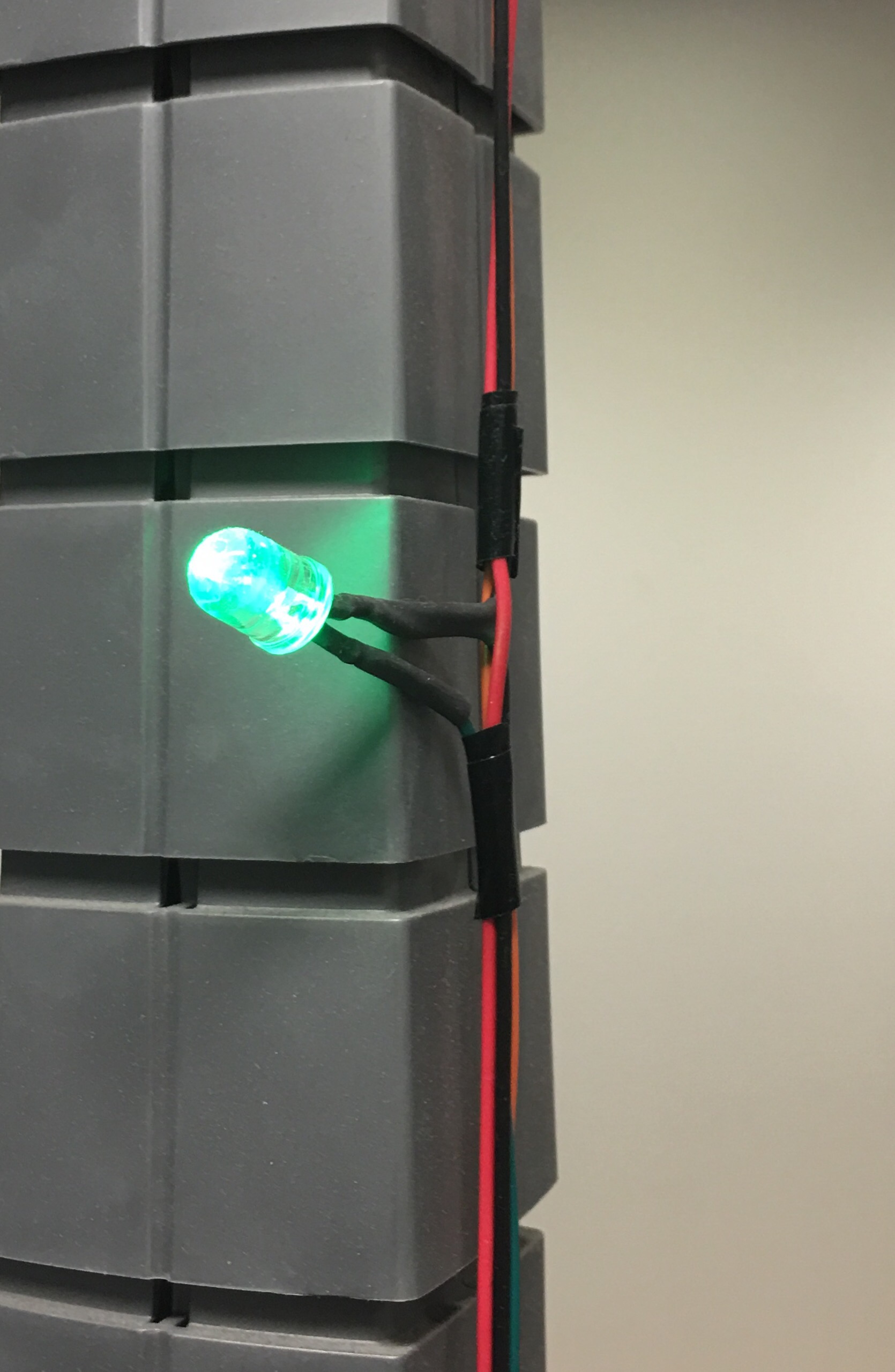
Below you can see one of the LED’s. It has the heat shrink around the joint. I have also used electrical tape to beaten up the wireing. 
Once you have the LEDs wired up, the next step is to wire up the power supply to light up the LEDs. I’ve chosen to power my LEDs through another USB port. The USB port provides 5V DC power which is enough to light them up.
First thing you have to do is cut off the end of a USB cable, You want to keep the Standard A side, that is the rectangular side,this will plug into the computer obviously.
There are 4 pins to the USB port, the outer pins are the power, the inner pins are the data.

To find out which pin is which to the wires, I used a multimeter. I just checked for resistance between the wire and the pin, if the resistance is zero, then you have a short and the wire matches the pin.
Cut away the data wires, you do not need them. Finally, wire up the USB port to the LEDs using the above circuit diagram as a guide
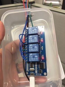
Test your traffic light with the software found on the USB Relays web site above and place into a plastic container to keep the circuit isolated.
You should now have a basic working traffic light.
You will just need to create traffic light stand, in my case I kept the lights raw and just taped them to a post at the office.
The traffic light should only draw 33mA with a 150 ohm resistor.
Find an old PC and hook up your traffic light.
The next step is to write software that will control the traffic light. To get the basics under python, there is an example already supplied on the USB Relay site as well, but I chose Java.
Java natively does not provide access to the serial ports, so I had to choose a library. I chose Java Simple Serial Connector. It provided a simpl interface that allowed me to communicate with the relay easily. To send each bit, I sent the HEX value for the byte i.e. 01 for bit 1, 02 for bit 2, 04 for bit 3 and 08 for bit 4.
If you want to do a combination of lights, for example bit 1 and 2, just send 03. It’s fairly simple once you play around with a basic program.
Changing lights is sub second speed, so you can I effects like rotating the lights before a change. The relay will also make a nice audible like a wheel of fortune wheel.
Unfortunately, due to my company owning the code to the traffic light even though I wrote it, I cannot include it here, but if you are using this for a build traffic light, you should be able to figure it out fairly easily.
If you end up building your own traffic light or have any issues, let me know in the comments or send me an email. My email is found in the About page.

